Water Level Indicator Using 7-Segment Display

![electronics-kits-india]()

![online-project]()

![Water-level-indicator-project-using-Arduino]()
![Water-Level-Indicator-Project]()
![electronics-kits-india]()
![simple-water-level-indicator-with-buzzer]()
![online-project]()
![Water-level-indicator-project-using-Arduino]()
![Water-Level-Indicator-Project]()


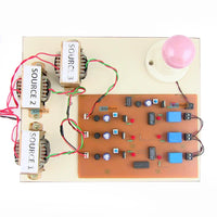
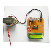
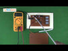
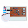
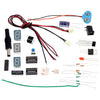
In this Water Level Indication Kit, we have made a water level indicator circuit, in which we will see the levels of water in 4 different levels, in which we will show 3 levels from the bottom to 3 different 7 segments, and for the fourth level of the last, we have used a buzzer. When the water reaches the first level then the first 7 segments will be displayed (L) and when the water level reaches the second level then (H) will be deployed on the other 7 segments and when the water level is at the third level (F) will be displayed on the third 7 segments and finally, when the water level reaches the fourth level, the buzzer will beep.
The buzzer sounds to indicate that Water Is Overflowing the tank and you need to switch off the motor pump. The kit Water Level Indicator Using 7- Segment Display circuit uses five wires to sense the different water levels in the tank. The bottom wire will connect to the negative terminal (GND) of the power supply. The other four wires are connected to the inputs of NOT gate IC 7404.

-21%


Water Level Indicator Using 7-Segment Display
Available:In Stock
- Product SKU: LGKT007
₹ 549
₹ 700
Need Volume Discounts? Deals are specially designed for you. Click here
Need Customization? Provide us more details Click here
🏠
Warehouse Details:


Specification
Description
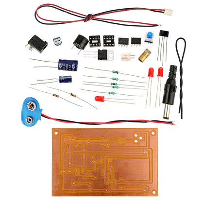
The motive of this science experiment is to learn how to make a Water Level Indication uses a 7-segment display. You can even discover ways to use a rectifier, diode, capacitor, and 7 segment displays and also discover ways to solder, and how to test the circuit.In this Water Level Indication Kit, we have made a water level indicator circuit, in which we will see the levels of water in 4 different levels, in which we will show 3 levels from the bottom to 3 different 7 segments, and for the fourth level of the last, we have used a buzzer. When the water reaches the first level then the first 7 segments will be displayed (L) and when the water level reaches the second level then (H) will be deployed on the other 7 segments and when the water level is at the third level (F) will be displayed on the third 7 segments and finally, when the water level reaches the fourth level, the buzzer will beep.
The buzzer sounds to indicate that Water Is Overflowing the tank and you need to switch off the motor pump. The kit Water Level Indicator Using 7- Segment Display circuit uses five wires to sense the different water levels in the tank. The bottom wire will connect to the negative terminal (GND) of the power supply. The other four wires are connected to the inputs of NOT gate IC 7404.
Block Diagram
Physical Attributes
- Dimensions (cm) L x W x H : 20 x 15 x 5
- Weight (gm): 200
Product Video
Related items


₹ 599.00
₹ 999.00


₹ 449.00
₹ 599.00


₹ 399.00
₹ 599.00


₹ 599.00
₹ 799.00