DC Motor Control Using A single Switch


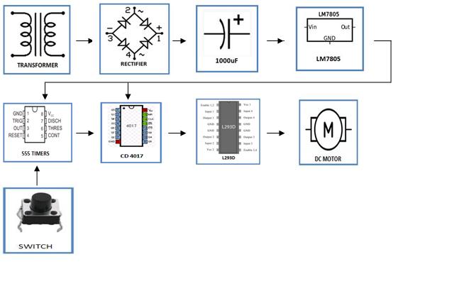
The kit DC Motor Control Using a Single Switch consists of three units- 555 as a monostable vibrator, as the decoder and flip-flop unit to hold the state and shift the bits and the motor drive unit to drive the motor in both the direction. All the controls of the motor are with the single switch that is forward-backward and stops. The 555 unit gives a trigger pulse on each press of the switch. To prevent false triggering 555 timers are used in monostable mode. Every trigger pulse changes the logic state of the output of the CD4017 which gives high polarity on different pins (+9V). The potential divider circuit distributes this voltage (formed by two equal 10K resistors V=4.5V).
These Motor Control Kit's signals are fed to the motor driver IC L293D to operate the motor in both the direction. The first press of the switch operates the motor in the forwarding direction by giving 4.5V to the signal pin. Similarly, the second press of the switch operates the motor in a backward direction by giving 4.5V to the signal pin. The third press of the switch will reset the IC CD4017 to give 0V output to both the signal pins and thus the motor stops.

DC Motor Control Using A single Switch
Available:In Stock
- Product SKU: LGKT048
₹ 799
₹ 999
Need Volume Discounts? Deals are specially designed for you. Click here
Need Customization? Provide us more details Click here
🏠
Warehouse Details:


Specification
Description
DC Motor Control Switch uses a Single Switch DC motor that will be run in the clockwise or anti-clockwise direction and stop using a single switch. It provides a constant voltage for the proper operation of the motor.The kit DC Motor Control Using a Single Switch consists of three units- 555 as a monostable vibrator, as the decoder and flip-flop unit to hold the state and shift the bits and the motor drive unit to drive the motor in both the direction. All the controls of the motor are with the single switch that is forward-backward and stops. The 555 unit gives a trigger pulse on each press of the switch. To prevent false triggering 555 timers are used in monostable mode. Every trigger pulse changes the logic state of the output of the CD4017 which gives high polarity on different pins (+9V). The potential divider circuit distributes this voltage (formed by two equal 10K resistors V=4.5V).
These Motor Control Kit's signals are fed to the motor driver IC L293D to operate the motor in both the direction. The first press of the switch operates the motor in the forwarding direction by giving 4.5V to the signal pin. Similarly, the second press of the switch operates the motor in a backward direction by giving 4.5V to the signal pin. The third press of the switch will reset the IC CD4017 to give 0V output to both the signal pins and thus the motor stops.
Block Diagram

Physical Attributes
- Dimensions (cm) L x W x H : 20 x 15 x 5
- Weight (gm): 200


